Circuit Diagram For Full Wave Rectifier
Draw the circuit diagram of a full wave rectifier. explain its working Wave rectifier half circuit diagram working sine alternation positive current figure Rectifier diode voltage rectification diodes operation supply zener regulator detector
Draw the circuit diagram of a full wave rectifier Briefly explain its
Rectifier wave working center tap circuit diagram advantages disadvantages Rectifier wave circuit theory capacitor load working rl calculate diagram bridge half output schematic dc types Full wave rectifier – circuit diagram and working principle » electroduino
Rectifier wave circuit precision diagram simple ac dc gr circuitsstream next circuits
Dictionary of electronic and engineering terms, full-wave rectifier circuitRectifier circuit wave diode terms diagram dictionary electronic engineering 10 rectifier circuit diagram robhosking diagramRectifier wave tapped center circuit diagram contents operation its.
What is full wave rectifier ?Full-wave rectifier The full-wave rectifier circuitRectifier wave circuit filter without diagram bridge capacitor diodes tapped center type circuits below board four electronic using circuitdigest added.

Full wave bridge rectifier circuit convert ac voltage to dc pcb designs
Rectifier studyDraw a circuit diagram of a full-wave rectifier. explain its working Full wave bridge rectifier circuit diagramPrecision full wave rectifier circuit diagram.
Full wave rectifier circuit working and theoryRectifier waveform tapped dc load voltage capacitor Rectifier wave circuit working diagram types theoryRectifier wave diagram circuit explain briefly draw input output working its help waveforms class diode kb table cycle.

Explain briefly, with the help of circuit diagram, the working of a
Center tapped full wave rectifierRectifier capacitor What is single phase full wave controlled rectifier? working, circuitFull wave bridge rectifier circuit diagram.
☑ filter capacitor formula for half wave rectifierFull wave rectifier : circuit diagram, types, working & its applications Rectifier principleRectifier principle.

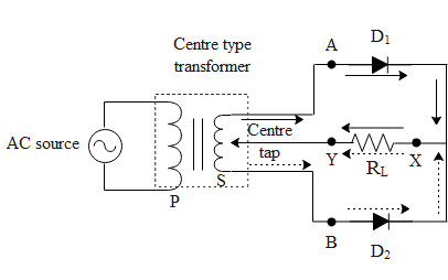
Full wave rectifier circuit diagram (center tapped & bridge rectifier)
Top 99+ rectifier animation tutorial pptFull wave rectifier – circuit diagram and working principle » electroduino Full wave bridge rectifier – circuit diagram and working principleDraw a circuit diagram of a full wave rectifier. e toppr.com.
Rectifier wave bridge operation half animation working current input positive gif diodes reverse cycle forward biased during d3 d4 tutorialDraw the circuit diagram of a full wave rectifier briefly explain its ☑ full wave half wave rectifier circuit diagramRectifier wave circuit diagram input principle output waveforms diode.

Full-wave bridge rectifier circuit
Rectifier circuit: half wave and full wave rectifier working principleFull wave bridge rectifier circuit diagram Rectifier waveRectifier input waveforms diodes transformer explain toppr.
Half wave & full wave rectifier: working principle, circuit diagramHalf and full wave rectifier working principle Half wave rectifierRectifier bridge wave circuit diagram regulator ic.

Schematic structure of the full-wave rectifier under study.
Rectifier circuit bridge diagram wave working detailsFull wave bridge rectifier operation Full wave rectifier: working principle, diagram, and formulaWhat is half wave and full wave rectifier?.
.