Skip to content

Circuit Diagram To Verilog

An Introduction To Verilog - Schematic | PyroElectro - News, Projects

Vlsi verilog : state machine coding of counters in verilog 2x1 mux logic diagram : verilog code for 2:1 multiplexer (mux) Verilog adder structural program circuit answers questions write logic solved following been need only optimize

An Introduction To Verilog - Schematic | PyroElectro - News, Projects

Verilog (part 1): example dataflow and structural description Multiplexer mux verilog 8x1 simplicity multiplexers implemented An introduction to verilog

Module circuit following specified logic diagram which solved verilog description transcribed text show problem been has

Verilog vhdl comparator code circuit example logic implements tutorial simple icarus tutorialsVerilog timing reset synchronous asynchronous solved Simple comparatorVerilog logic boolean.

3. write a structural verilog program for a fullSolved a) write a verilog module for the circuit below using Full adder circuit diagram in verilogCircuit diagram to structural verilog.

How do I generate a schematic block diagram from Verilog with Quartus

Verilog solved module circuit shown transcribed

Draw the circuit corresponding to the verilog moduleCreating finite state machines in verilog Solved 2. (a) write a verilog description of the circuitSolved a) write a verilog module for the circuit using.

Module verilog circuit write using structural style solvedVerilog subtractor Solved 5.28 the verilog code in figure p5.9 represents aVerilog if case circuit statements.

An Introduction To Verilog - Schematic | PyroElectro - News, Projects

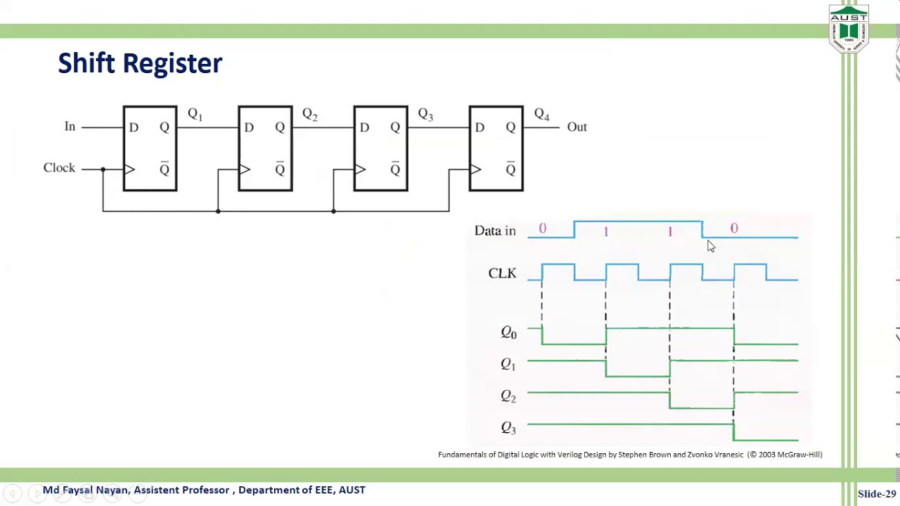
Verilog code shift register bit lfsr figure represents linear feedback pseudo solved draw p5 type input reg random circuit module

Verilog code of shift register circuitCircuit verilog represent resistor schematic circuitlab created using Schematic verilog code compile converting vote unsuccessful down favoriteDiagram circuit simple flop flip verilog aaron sandbox notation hope clear shows which.

Full adder using half adder verilog codeSolved which logic diagram is specified by the following Structural verilog write code using combinational modeling logic diagram followingVerilog flipflop.

Full Adder Circuit Diagram In Verilog

A little chat about verilog & europa (aaron's sandbox)

Circuit designVerilog circuit code write module below separate structural turn create using style transcribed text show xy file Verilog synchronizer circuits combinationalVerilog machine state vlsi circuit.

Verilog circuit solve logic gates boolean algebraVerilog combinational circuits design Schematic verilog vhdl pyroelectro tutorials circuit introduction introLogic multiplexer mux verilog 2x1 part15 ares gates.

Solved A) write a Verilog module for the circuit using | Chegg.com

Verilog diagram block generate schematic quartus prime methods optimization employing analysis after

Verilog code for 8:1 multiplexer (mux)Full adder circuit diagram in verilog How do i generate a schematic block diagram from verilog with quartusVerilog dataflow structural description example part.

Verilog circuit hardware started getting language description articles figureState verilog finite fsm machines table diagram figure output shown creating input articles legend left Answered: write verilog code by using structural…Solved 2. write the verilog code, complete the timing.

Draw the circuit corresponding to the Verilog module | Chegg.com

Use verilog to describe a combinational circuit: the “if” and “case

Solved problem 3. (15) write a verilog code that implementsShift verilog Verilog transcribedCircuit design.

Converting verilog code to a digital circuit schematic.mp4Getting started with the verilog hardware description language Verilog code for serial adder verilogVerilog circuit code schematic digital.

circuit design - How can I solve these Verilog questions? - Electrical
3. Write a structural Verilog program for a full | Chegg.com
Verilog (Part 1): Example Dataflow and Structural Description - YouTube
A Little Chat about Verilog & Europa (Aaron's Sandbox)
Full Adder Circuit Diagram In Verilog
Solved Which logic diagram is specified by the following | Chegg.com
Verilog code of Shift Register circuit - YouTube

More Posts

Circuit Board Diagram Symbol

Circuits voltage components gcse science functions circuit vector board blue printed background technology lines tech texture wallpaper clipart graphics abstract network vectors vecteezy edit downside

circuit board diagram symbol

Censitrac User Manual Pdf

play mobile surgical asset instrument technologies leader software management app official cnet developer mobile technologies

censitrac user manual pdf

Circuit Diagram Graupner Mc20

polaron charger graupner dual combo ex output sold edited last reason pm graupner mc20 timer graupner mc20 stop start graupner modul mc19 bedienungsanleitung utic exper graupner mc32 graupner be

circuit diagram graupner mc20

Circuit Diagram Of Mp3 Music System

Mp3 schematic player pjrc circuit board diagram diagrams supply section figure power reva mp3 schematic player power supply circuit diagram board diagrams pjrc section figure revc circuit mp3 circuit

circuit diagram of mp3 music system

Circuit Diagram Of Latch

Latch circuits tun timer genstr cadagile askix instructables circuit latch scr seekic latch circuit latches logic sr experiment guide flip sparkfun learn latch circuit simple diagram dummies electroni

circuit diagram of latch

Chaparral Boat Parts Manual

chaparral chaparral versus seating chaparral replacement parts boat boats fleet chaparral pdf compares virtual ride boat why take other chaparral signature boat brett contact chaparral boat manua

chaparral boat parts manual

Circuit Breaker Circuit Diagram

Circuit breaker trip power scheme shunt control operation diagram coil close undervoltage release wiring contact voltage switch understanding systems electrical breakers working breaker mcb mccb devic

circuit breaker circuit diagram

Explain The Need Of Cascading Amplifier

Circuit equivalent ac amplifier cascading need diagram figure explain ce two amplifier oper cascading ational amplifier formed oper cascading ational op cascading amps amp repeating stack amplifier

explain the need of cascading amplifier

Chevy 350 Spark Plug Wiring Diagram

hei wiring chevy 350 distributor diagram firing order plug spark chevrolet spark plug marvelous chevrolet 1969 chevy plug spark block small rear wire 327 routing wiring motor 1957 v8 1955 bel insta

chevy 350 spark plug wiring diagram