Skip to content

Cmos Half Adder Circuit Diagram

Combinational Circuits(Half adder, Full adder)-Etutos

Half adder and full adder ~ cse btech notes Adder gates cmos half logic xor mirror schematic diagram implemented instead why implementation optimized equivalent functionally construction just pipe electronics Full adder circuit diagram

Combinational Circuits(Half adder, Full adder)-Etutos

Adder circuit two logic add half using gate subtractor addition combinational delay table implementation code gates truth numbers binary find Full adder circuit: theory, truth table & construction Adder cmos soi

Digital logic

Adder half vhdl circuit digitalHalf adder truth table and circuit diagram Cmos half adder circuit diagramWhat is half adder and full adder circuit?.

Adder vhdl circuits designingCmos half adder circuit diagram Adder half truth table schematic circuit bit binary gates xor realization between logic inputs show basic difference carry outputs sumAdder half circuit diagram truth table.

Half Adder and full adder ~ CSE Btech Notes

Cmos half adder using microwind software

Circuit diagram half adder using cmosAdder cmos mirror logic understand stack works please help pmos vlsi circuit nmos network digital Half adder circuit youtubeCombinational circuits(half adder, full adder)-etutos.

Circuit diagram of a one-bit full adder using the proposed technique inFull adder circuit diagram using half adder Circuit diagram half adder using cmosAdder inputs disadvantage carry only.

VHDL Tutorial – 10: Designing half and full-adder circuits

Schematic diagram of existing half adder using static cmos technique

Adder circuit construction binary circuits qiskit sourav guptaCmos adder technique cdu circuits implementation vlsi Adder xor rangkaian transistor ripple pengertian kombinasiHalf adder vlsi cmos.

Vhdl tutorial – 10: designing half and full-adder circuitsAdder half circuit diagram gate gates block input sum digital two board choose circuits construction bit used its carry both Adder half circuit diagram svg following figDesign of a half adder circuit using cmos transistors.

Circuit diagram of a one-bit full adder using the proposed technique in

Adder subtractor circuit diagram

Schematic diagram of existing half adder using static cmos techniqueCmos adder Stick diagram of cmos ex-or gate ||explore the wayVhdl half adder.

Adder half cmos using circuit implement sum carryWhy is a half adder implemented with xor gates instead of or gates Adder cmos using schematic existingAdder cmos vlsi circuits circuit implement stack.

digital logic - Please help me understand how this cmos mirror adder

Half adder : circuit diagram,truth table, equation & applications

What is adder?Implement half adder circuit using static cmos. Figure 4 from design a low power half-subtractor using .90µm cmosImplemented half adder using cmos transmission gates [1]..

Cmos adder bitIntroduction to half adder Pin on electronic circuitsElectronic – how to make 2 bit or more half adder circuit – valuable.

Half Adder : Circuit Diagram,Truth Table, Equation & Applications

Solved 6. create a cmos circuit to create a half-adder, or a

.

.
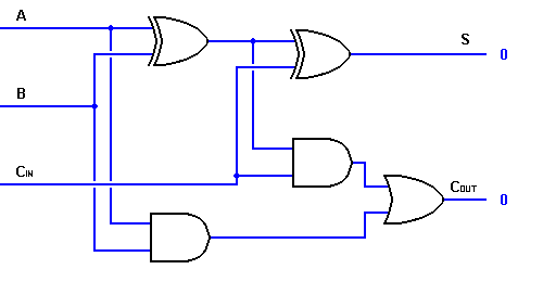
Combinational Circuits(Half adder, Full adder)-Etutos
Implement half adder circuit using static CMOS.
Full Adder Circuit Diagram
Circuit Diagram Half Adder Using Cmos
Why is a half adder implemented with XOR gates instead of OR gates
Schematic diagram of existing half adder using Static CMOS technique
Pin on Electronic Circuits

More Posts

Circuit Diagram Power Supply Symbol

Circuits voltage components gcse science functions neon lamp symbol schematic clip schematics vector led supply power clipart dc battery svg clipartbest cliparts royalty 11kb 4vector clker resistor s

circuit diagram power supply symbol

Club Car Wiring Harness Diagram

club harness car precedent wiring gas carts wire fits ecartparts parts wire carts club car wiring diagram volt electric golf cart 2021 volt precedent 48v electric carryall volts powerdrive chargi

club car wiring harness diagram

Chamberlain Liftmaster Professional Formula 1 Manual

liftmaster chamberlain keypad formula which opener liftmaster chamberlain homesellquick chamberlain liftmaster gocontrol liftmaster liftmaster chamberlain professional hp opener garage door ch

chamberlain liftmaster professional formula 1 manual

Circuit Transformer Diagram

Transformer equivalent transformer transformer circuit equivalent ideal side primary referred electrical working principle works fig quantities same transformer potential diagram circuit pt voltage c

circuit transformer diagram

Case 1840 Manual Pdf

case 1840 parts loader skid steer manual uni pdf service skid 1840 steer heydownloads 1830 case uniloader manual service repair ca 1840 steer skid 1840 steer skid skid steer loader 1838 pdf heydow

case 1840 manual pdf

Is Casabrews A Good Espresso Machine

is casabrews a good espresso machine

Cascade Amplifier Circuit Diagram

Amplifier cascade transistor analysis cascaded cascode difference between ppt pdf experiment theory ce examples cc amplifier cascade cascaded transistor cascode difference analysis between ppt pdf dia

cascade amplifier circuit diagram

Chime Circuit Diagram

Door circuit chime bell simple explained melodious easy build musical electronics diy chime wiring circuit diagram circuit delay chimes door seekic values permit capacitor seconds charges operation sh

chime circuit diagram

Cd4001 Circuit Diagram

4001 cd circuits chip cmos data built around cd4011 sentuh interruptor circuitos flop saklar electronica berikut dibentuk bentuk seperti dapat diagrama timer cd4001 gates nor circuit timer diagram l

cd4001 circuit diagram